Control device: LCD controller
Product structure: small size, large flow, simple structure, ATS-integrated
features: fast switching speed, low failure rate, easy maintenance, reliable performance (with automatic switching time adjustable 1s-99s) ��Front-board wiring
conversion mode: grid to grid, grid to generator, self-turning and self-recovering, self-turning and not self-recovering, each other is a standby product. Poles: 2, 3, 4
 dual power automatic transfer switch")
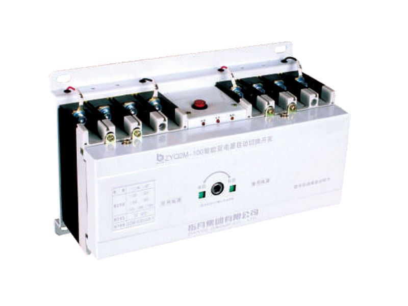
ZYQ2M (terminal type) dual power automatic transfer switch
Main purpose and scope of application
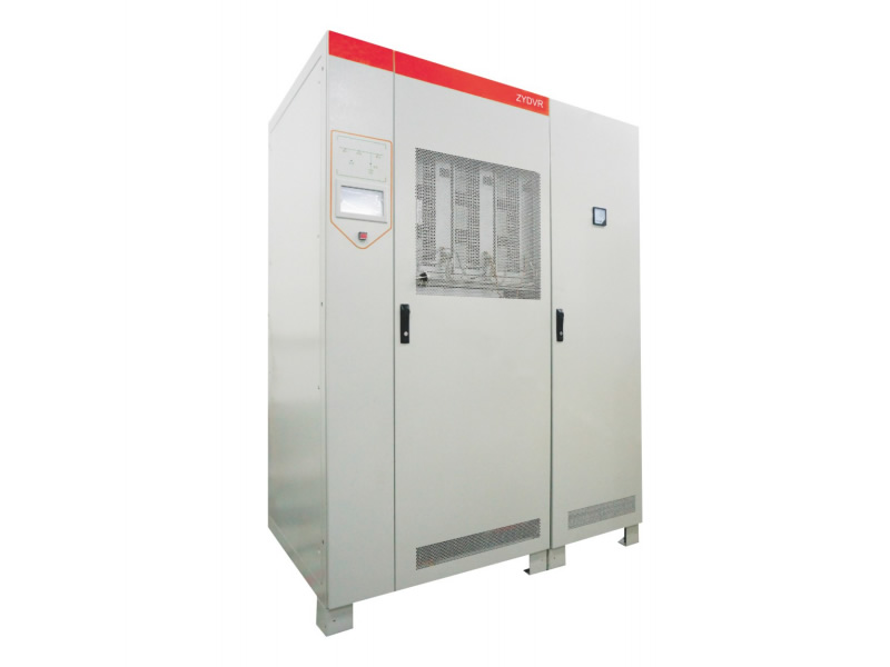
This switch is suitable for 50/60Hz, rated working voltage 380V, rated working current 20-1250A dual power supply switch, can realize automatic or manual switching between common power supply (N) and standby power supply (R) . (The main and backup power supply can be the power grid, starter generator set, battery, etc. The main and backup power supply is determined by the user.) The dual power supply customers can realize unattended operation. This switch is suitable for special or first-level load users restricted by the country, such as high-rise buildings, post and telecommunications, coal mine ships, industrial assembly lines, medical and health, military facilities, airports, fire protection, metallurgy, chemical industry, textiles, petroleum, etc., which do not allow power outages. place.
This product complies with: National Standard GB/T14048.11-2008.
Model and meaning

Product overview
Control device: LCD controller
Product structure: small size, large flow, simple structure, ATS-integrated
features: fast switching speed, low failure rate, convenient maintenance, reliable performance (with automatic switching time adjustable 1s-99s) Wiring mode: wiring in front of the board.
Conversion mode: grid to grid, grid to generator, self-turning and self-recovering, self-turning and not self-recovering, mutual backup. Product pole number: 2, 3, 4
Product standard: GB/T14048.11-2008
ATSE: CB level, with overload and short circuit protection
. Product frame: 63 100 225 400 630 800 1250
Product current: 20 32 40 63 80 100 125 160 200 225 250 315 400 500 630 800 1000 1250
Product category: Circuit breaker (CM1 TQ30 )
Normal working conditions
1. The ambient air temperature is -5��C~+40��C, and the 24-hour average value does not exceed +35��C;
2. The relative humidity does not exceed 50% when the highest temperature is +40��C, and higher is allowed at lower temperatures Relative humidity, such as 90% at +20��, but it should be taken into account that condensation may occur due to temperature changes;
3. The altitude of the installation site does not exceed 2000m;
4. The category is ��, and the inclination is not greater than �� 23��;
5. Pollution level is 3;
6. If the above conditions are not met, the manufacturer should be consulted when ordering, and the switch should be used in mining, offshore, petroleum, and nuclear power plants to sign a separate technical agreement.
Technical parameters of ZYQ2 terminal type M
��Basic structure
ZYQ2M series automatic power transfer switch is mainly composed of power conversion actuator, circuit breaker and controller. The dual power switch has automatic and manual functions. Power indicator, common closing indicator, standby closing indicator and other working status. The switch has the characteristics of small size, long life, low power consumption, light weight, stable operation and convenient use.
��Installation and use method When
installing the wiring, the common power supply N should be connected to the common power supply to execute the circuit breaker QN, and the backup power supply R should be connected to the standby power supply to execute the circuit breaker QR. When QN and QR are four-wire circuit breakers, the wiring method is according to the wiring diagram, where 1, 3, and 5 of QN and QR are three-phase (A, B, C) inlet terminals, and 2, 4, and 6 are three-phase outlets Terminal, 7 is the neutral line (N) incoming end, 8 is the neutral line outgoing end. If a three-pole circuit breaker is selected, the neutral wire (NN) of the common power source N and the neutral wire (NR) of the standby power source R must be connected to the three-pole dedicated neutral wire terminal KG. See the wiring diagram for specific protection. The working power of the automatic controller of the dual power transfer switch is the A phase and the neutral line N of the inlet end of the circuit breaker QN and QR. During the installation and wiring of the automatic power switch, do not connect the original machine to the inlet end of the circuit breaker. The sampling signal line of the controller is forgotten to be disconnected or short-circuited, otherwise it will not work normally.
��
Select the automatic working state for the operation . The default closing is common when the machine is turned on. For manual operation, the manual-auto button should be placed in the manual operation position. When the handle is rotated clockwise to the terminal, the common power supply performs QN closing of the circuit breaker and standby The power supply executes the circuit breaker QR opening; when the handle is pushed counterclockwise to the terminal, the backup power supply executes the circuit breaker QR closing; the common power supply executes the circuit breaker QN opening.
ZYQ2 integrated Z technical parameters
��Intelligent controller function
ZYQ2 intelligent dual power transfer switch. The controller is input by keyboard position and (LCD) liquid crystal display. It can detect the common power (N) and standby power (R) three-phase and four-wire synchronously: it has the detection function for phase loss, voltage loss, and power failure. If it is lower than 80% of the rated working voltage value, it is judged as a voltage loss. The backup power supply (R) will give an alarm. The computer will process the detection result and send out the corresponding instruction. The processing result can be displayed on the (LCD), giving the user a good With the human-machine dialogue interface, the microcomputer detects abnormal data and enters the double-divided state after delay. After a delay (0-30s), it will switch to normal power supply.
��Structure and function The
switch has three states for users to choose: common power supply (N) closed, standby power N points, standby power R point switch has the characteristics of small size, light weight, stable performance, and convenient use.
��
Auto-transfer andself-recovery (R) The power griddefaults to automatic and common power supply. When the power supply is abnormal (any phase is lost or broken), NA, NB, NC, RA, RB, RC on the controller LCD will respond disappear. The normal power supply (N) is abnormal. After a delay of 3s, it is switched to the standby power supply (R). The delay time can be set to 0~30s, and it is set to 3s at the factory. When the common power supply returns to normal, it will automatically switch from the backup power supply to the common power supply (N); when the backup power supply (R) is abnormal, the controller will sound a "beep" alarm. The alarm can also be considered closed. The disappearance of "Alarm" on the LCD means that the alarm system has been closed, and there is no "Alarm" function at this time. Press the minus key to display the word "alarm". At the same time, a beep will sound, indicating that the alarm system has been turned on.
��Auto-input and self-recovery (F) grid
The controller detects the common power source (N) and the generating power source (R). When the common power source (N) is abnormal, the control system sends a generating command (normally open contact) to the generator set to start the generator set. When the generator set voltage reaches Under normal working voltage value, the controller issues an instruction to put the power generation power into use to ensure the normal operation of the generator set. When the generator voltage is lower than 75% of the rated value, the control system will automatically disconnect the load and enter the double-divided state. When the grid voltage (N) returns to normal, the intelligent system will automatically return to the normal power supply (N) from the standby power supply (R) after a delay, and the generator set must be manually shut down.
Shape and installation dimensions

| Model (end) | Dimensions | Installation size | |||
| W | L | H | W1 | L1 | |
| ZYQ2M-100/3P | 288��203��120 | 253��184 | |||
| ZYQ2M-100/4P | 318��210��140 | 283��190 | |||
| ZYQ2M-225/3P | 330��215��156 | 296��194 | |||
| ZYQ2M-225/4P | 365��215��156 | 333��194 | |||
| ZYQ2M-400/3P | 465��310��190 | 410��285 | |||
| ZYQ2M-400/4P | 508��310��190 | 455��285 | |||
| ZYQ2M-630/3P | 528��318��195 | 478��295 | |||
| ZYQ2M-630/4P | 588��318��195 | 535��295 | |||
| ZYQ2M-800/3P | 608��334��190 | 556��310 | |||
| ZYQ2M-800/4P | 678��334��190 | 626��310 | |||
| ZYQ2M-1250/4P | 695��391��280 | 642��365 | |||
| ZYQ2M-1600/4P | 695��391��280 | 642��365 | |||
| ZYQ2Z-100/3P | 388��222��120 | 355��200 | |||
| ZYQ2Z-1004P | 420��222��120 | 385��200 | |||
| ZYQ2Z-225/3P | 430��222��140 | 393��203 | |||
| ZYQ2Z-225/4P | 466��222��140 | 433��203 | |||
| ZYQ2Z-400/3P | 562��310��190 | 510��286 | |||
| ZYQ2Z-400/4P | 606��310��190 | 555��286 | |||
| ZYQ2Z-630/3P | 626��318��195 | 572��295 | |||
| ZYQ2Z-630/4P | 690��318��195 | 637��295 | |||
| ZYQ2Z-800/3P | 707��340��190 | 655��315 | |||
| ZYQ2Z-800/4P | 778��340��190 | 728��315 | |||
| ZYQ2Z-1250/3P | 732��480��280 | 675��365 | |||
| ZYQ2Z-1250/4P | 802��480��280 | 745��365 | |||
| ZYQ2Z-1600/3P | 732��480��280 | 675��365 | |||
| ZYQ2Z-1600/4P | 802��480��280 | 745��365 | |||
Function description of intelligent multi-function dual power controller
 This controller is used in dual power transfer switches. The main components are selected from imported large-scale Harvard structure microcomputer chips. It is a stable and reliable working performance, few peripheral components, high anti-interference performance, anti-misoperation, anti-crash, and anti-garbled , Anti-lost data, low temperature rise, maintenance-free, no internal adjustment components, all adjustments are completed by pure software. The hardware and software have reached the international advanced level.
The controller is input by the keyboard position and (LCD) large liquid crystal display, and synchronously detects the common power supply (N) and standby power supply (R) three-phase four-wire (overvoltage, undervoltage, phase failure, loss of voltage, power failure), etc. When it is higher than 115% of the rated working voltage, it is judged as overvoltage, and when it is lower than 80% of the rated working voltage, it is judged as undervoltage. The anti-misoperation function is designed for the sudden change of working power peak. Standby fault alarm (also can be turned off manually). The microcomputer processes the test results accordingly, and then sends out the execution instructions, and the processing results are displayed on the (LCD). Give users a good man-machine dialogue interface. The default automatic and common working mode is initialized after power-on.
Power supply (overvoltage, undervoltage, phase loss, loss of voltage, power failure) and other abnormal conditions, the microcomputer will enter the double division after detection, after a delay (Os 30s is factory set to 3s), then the standby power supply will work. (If the standby power supply is abnormal at the same time, it enters the double-divided state, and the power supply returns to normal has priority to work). Abnormal conditions such as overvoltage, undervoltage, phase failure, loss of voltage, power failure, etc. occur in the standby power supply, and a "beep, beep" alarm sound will be emitted at the same time.
Automatic switching and automatic recovery: The common power supply has an abnormal situation, and it is delayed by double points. Then put in standby power to work. When it is detected that the common power supply returns to normal, it will automatically return to the common power supply to work and supply power from standby.
Description of intelligent multi-function dual power supply control function
Self-turning and non-returning: The common power supply has an abnormal situation, after the double-division delay, then the standby power supply is turned on. When it is detected that the common power supply returns to normal, it will not automatically return to the common power supply for power supply.
Power grid and power grid: The controller detects that the common and backup power sources come from two power grid transformer voltages.
Power grid and power generation: The controller detects that the common power source comes from the grid transformer and the backup power source comes from the voltage of the self-provided generator set. The generator set can be automatically started when the common power supply is turned off. When the voltage of the generator set returns to the normal range value, the generator starter can be automatically turned off. When it is detected that the common power supply returns to normal. Then it will automatically return to the normal power supply from standby.
Fire-fighting (EPS) 24V: This machine uses more advanced electronic fire-fighting functions, which are more stable and reliable than traditional electromagnetic shunt fire-fighting. Both AC and DC (15V-30V) voltage can work normally, and DC has no positive and negative poles. Working current (30MA) is about.

If you have any enquiry about quotation or cooperation,please free to email us ata65148373@163.comor use the following enquiry form,Our sales representative will contact you within 24 hous.thank you for your interest in our products.
Share our Product over the Social Networks
Search across our website
 English
 ��(ji��n)�w����