1. Ambient temperature: ambient air temperature is -5��C-+40��C (special order must be negotiated with the manufacturer);
2. Altitude: The altitude of the installation site is 2000mm;
3. Pollution degree: Pollution degree is 3;
4. Installation position: it should be installed vertically, with an inclination not exceeding 5��;

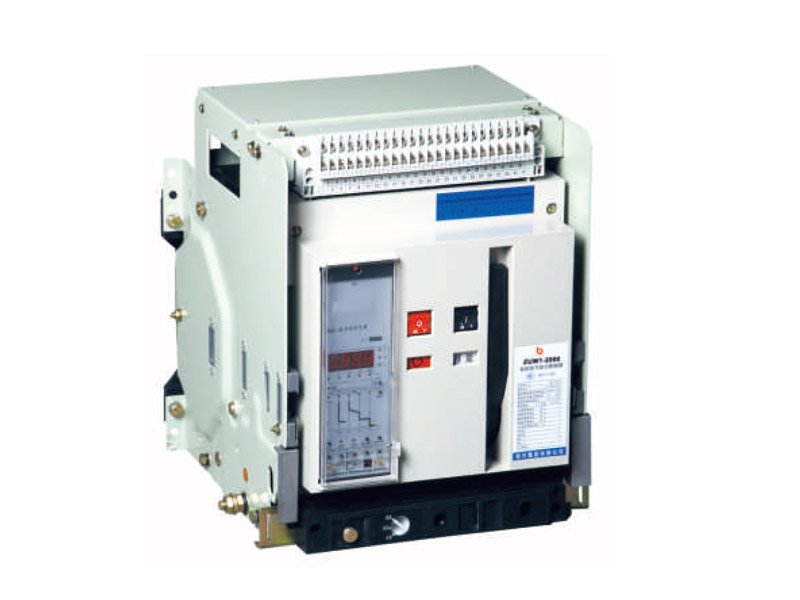
ZUM1 Intelligent universal circuit breaker
Main purpose and scope of application
This series of intelligent universal circuit breakers (hereinafter referred to as circuit breakers) are suitable for AC 50Hz, rated working voltage of 380/660V, rated current of 630/3200A in the distribution network, mainly used to distribute electrical energy And to protect the circuit and power supply equipment from overload, undervoltage, short circuit, grounding and other faults. The circuit breaker has an intelligent protection function, selective protection is accurate, can improve power supply reliability, avoid unnecessary power outages, and has an open communication interface, which can realize remote control, remote adjustment, remote measurement, and remote communication to meet centralized control Requirements for centers and automation systems. This product complies with: National Standard GB14048.2.
Model and meaning

Working conditions
1. Ambient temperature: ambient air temperature is -5��C-+40��C (special order must be negotiated with the manufacturer);
2. Altitude: The altitude of the installation site is 2000mm;
3. Pollution degree: Pollution degree is 3 level;
4, installation location: should be mounted vertically, maximum slope [deg.]. 5;
. 5, installation categories: a main circuit and undervoltage trip coil, power transformer primary winding mounted category IV, the rest of the secondary circuit, a control circuit for the installation Category III;
6. Isolation function: Withdrawable circuit breaker has an isolation function;
7. Environmental protection: environmental protection factors are fully considered in the design and manufacturing, and most parts are made of recyclable and naturally degradable materials;
Main technical parameters The main technical parameters of the
circuit breaker (see Table 1)
Table 1
| model | Rated current In(A) | Rated working voltage | Rated insulation voltage | Rated ultimate short-circuit breaking capacity Ics kA | Rated short-circuit breaking capacity Icu kA | Rated short-time withstand current Icw kA(1s) | Arcing distance |
| Ue V | Ui V | 380V 660V | 380V 660V | 380V 660V | mm | ||
| ZUW1-2000 | 400, 630, 800, | 380 or 660 | 660 | 65 50 | 40 40 | 40 40 | 0 |
| 1000, 1250, | |||||||
| 1600, 2000, | |||||||
| ZUW1-3200 | 2000, 2500, | 80 65 | 50 65 | 65 50 | |||
| 2900, 3200, |
Intelligent overcurrent release protection characteristics
a. The setting Ir value and error of the release (see Table 2)
Table 2
| model | Long delay | Short delay | Instantaneous | Ground Fault | ||||
| lr1 | error | lr2 | error | lr3 | error | lr4 | error | |
| ZUW1-2000 | (0.4~1ln) | ��10% | (0.4~15ln) | ��10% | 1.0ln~50kA+OFF | ��15% | (0.2~0.8)ln (maximum 1200A, minimum 160A) | ��10% |
| ZUW1-3200 | 1.0ln~75kA+OFF | |||||||
Note: When there is a third-stage protection requirement at the same time, the setting value cannot be crossed.
b. Long delay overcurrent protection inverse time action characteristic I2TL=(1.5lr1)2tL, among which (1.05~2.0)lr1 action time (see Table 3), the time error is ��15%.
table 3
| 1.05lr1 | 1.03lr1 | 1.5lr1 setting time (s) | 15 | 30 | 60 | 120 | 240 | 480 |
| >2h no action | <1h no action | 2.0lr1 setting time (s) | 8.4 | 16.9 | 33.7 | 67.5 | 135 | 270 |
Note: tL-long delay, 15lr1 setting time, TL-long delay action time.
c. Short-time overcurrent protection characteristics: the protection characteristics of the release are inverse time characteristics at low multiples. Its characteristic I2T2Ts=(8lr1)2ts, ts is the short delay setting time. When the overload current is greater than 8lr1, it will be automatically converted to the definite time characteristic, and its definite time limit and characteristic (see Table 4), the time limit error is ��15%.
d. The ground fault protection characteristic is a definite time limit, and its time delay characteristic (see Table 4)
Table 4
| Extended time s | Return time s | ||||||
| 0.1 | 0.2 | 0.3 | 0.4 | 0.06 | 0.14 | 0.23 | 0.35 |
Wiring diagram
Circuit breaker control circuit wiring diagram

|
1, 2- auxiliary power input 3, 4, 5- fault trip contact output terminal, 4 of which is the common terminal 6, 7- circuit breaker status first group auxiliary contact output terminal 8, 9- circuit breaker status second group Auxiliary contact output terminal 10-Communication interface lead wire A terminal 11-Communication interface lead wire B terminal 12, 13-The first group signal contact output terminal 14, 15-The second group signal contact output terminal 16, 17-No . 3 groups of signal contact output terminals 18, 19- 4th group of signal contact output terminals 20- protective ground wire 21- N-phase voltage input terminal 22- A-phase voltage input terminal 23- B-phase voltage input terminal 24-C-phase voltage Input terminal 25, 26-external transformer input terminal |
SB1-shunt button SB2-emergency disconnect button SB3-close button SB4-motor energy storage button Q-undervoltage (instantaneous or delayed) trip F-shunt trip X-closed solenoid M-storage Energy Motor SA-Motor Limit Switch XT-Terminal Terminal DF-Auxiliary Switch |
35- can be directly connected to the power supply (automatic pre-storage) The dotted line part is self-connected by the user. If the Q, F, X, M intelligent controllers have different rated voltages, they can be connected to the power supply separately. When the smart controller is DC, 1 is the positive pole and 2 is the negative pole. Fu-fuse (self-prepared by the user) J-relay normally open (prepared by the user), remote control to open the circuit breaker. This wiring diagram is only applicable to L and M type controllers and four normally open and four normally closed contacts. If the user needs H type controller and other types of auxiliary contacts, the wiring diagram will be provided separately. |
Overall and installation dimensions
ZUW1-2000 fixed circuit breaker installation dimensions, overall dimensions (see Figure 1 and Table 5)

ZUW1-3200 fixed circuit breaker installation dimensions, overall dimensions (see Figure 2 and Table 6)

ZUW1-2000 withdrawable circuit breaker installation dimensions, overall dimensions (see Figure 3 and Table 7)

ZUW1-3200 withdrawable circuit breaker installation dimensions, overall dimensions (see Figure 4 and Table 8)

Panel cut-out installation dimensions (see Figure 5 and Table 9)

If you have any enquiry about quotation or cooperation,please free to email us ata65148373@163.comor use the following enquiry form,Our sales representative will contact you within 24 hous.thank you for your interest in our products.
Share our Product over the Social Networks
Search across our website
 English
 ���w����