1. The altitude is not higher than 2000 meters.
2. The ambient temperature is -20��C to 45��C.
3. The air humidity does not exceed 50% at 40��C, and does not exceed 90% at 20��C.
4. The surrounding environment has no corrosive gas, no conductive dust, and no flammable and explosive media.

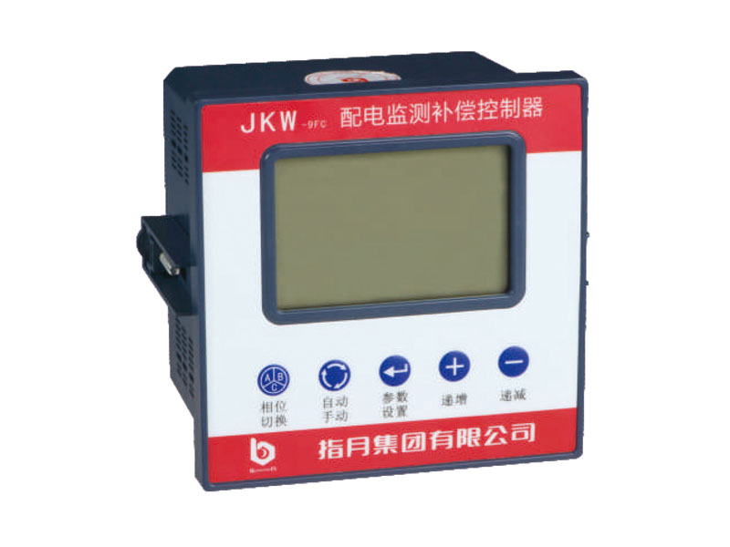
JKW-9FC/9SC Intelligent capacitor power distribution monitoring compensation controller
Main purpose and scope of application
JKW-9 port C series intelligent capacitor power distribution monitoring and compensation controller is a special controller used in conjunction with the company��s ZUIC-9 series, ZUIC-7 series, and ZUIC-9K series intelligent capacitors. After that, it will automatically register, arrange and optimize the smart capacitor parameters in the entire network, so that they become an organic whole, and users can work normally without setting any parameters. Detect grid parameters in real time and automatically control the switching of smart capacitors through communication commands according to the requirements of the control parameters, so that the power factor of the grid can be stabilized within the range specified by the user in real time, reducing line loss, increasing the output capacity of the transformer, and improving the quality of power supply. Products with communication have the ability to store analysis data at intervals of 1 day and basic power parameters at half an hour intervals, and the storage time is as long as 21 months (after 21 months, it will be automatically covered in units of months); these historical data can be Download to the PC through the RS485 interface, and then use the background software to automatically generate curves, tables, and bar graphs to view, so that the load changes and power quality of the past two years are under control.
This product symbol: industry standard JB/T9663-2013 (our company is the main drafting unit of this standard).
Features
1. Calculate the switching capacitor capacity based on the fundamental reactive power, which can avoid various forms of switching oscillations, and can correctly display the power factor of the power grid in the presence of harmonics.
2. High power factor measurement accuracy and wide display range.
3. Up to 32 loop smart capacitors can be controlled.
4. Shortcut function keyboard, large LCD display, Chinese operation, friendly man-machine interface and convenient operation.
5. Various control parameters are all digitally adjustable, intuitive and easy to use.
6. There are 3 working modes: automatic operation, manual operation and remote control.
7. With power failure protection function, the control parameters will not be lost after power failure.
8. The automatic identification function of the total C Ding.
9. Automatic networking, no need to set the network address of the smart capacitor.
10. It has the functions of over-voltage, under-voltage, phase loss, temperature protection, and distortion rate over-standard protection.
11. The current signal input impedance is low ��0.01 ohm.
12. The target power factor adjustment range is wide.
13. With RS485 communication interface.
14. With MODBUS-RTU communication protocol, it is convenient to communicate with concentrator or upper computer.
15. Power distribution monitoring terminal products have storage curve data and daily statistical data. The curve data is stored every half an hour, and the daily statistics data is frozen at zero o'clock every day.
16. The controller with communication function produced by the company is equipped with free application background software (users can download and install on the company's website), this software can run on windows-2000-XP windows operating system, the entire software is a graphical interface , The operation is simple, and many operations can be completed by clicking the mouse. The main functions include remote modification of control parameters, viewing of control parameters, viewing of power parameters, viewing of capacitor bank switching status, remote switching of capacitor banks, etc., and provides communication protocols to facilitate users Secondary development. At the same time, it integrates software tools for automatic generation of compensation schemes, serial port debugging software tools, etc.
Main technical parameters
1. Power supply voltage: 380V (UaһUc) ��20%;
2. Signal current: AC 0-55A (If the sampling current is greater than 5.5A, a power factor display error will occur);
3. Operating frequency: 45- 65Hz;
4. Minimum operating current (sensitivity): 5OmA;
5. RS485 load strength: 32;
6. Installation method: embedded installation inverted tooth accessory screw fixing;
7. Dimensions: length (l2Omm) X width (12Omm) ) X depth (87mm);
8. Signal voltage: AC5OV-275V (phase voltage);
9. Undervoltage threshold: 176V;
10. Protection level: enclosure IP30;
11. Energy consumption of the whole machine: <6VA;
12. Connection method ��The pluggable terminal is fixed with screws;
13. Installation size: physical size 1l2mm �� l12mm, opening size 1l3mm �� l13mm;
Description of available models

Working conditions
1. The altitude is not higher than 2000 meters.
2. The ambient temperature is -20��C to 45��C.
3. The air humidity does not exceed 50% at 40��C, and does not exceed 90% at 20��C.
4. The surrounding environment has no corrosive gas, no conductive dust, and no flammable and explosive media.
5. There is no severe vibration at the installation site.
Panel diagram

Character LCD panel


Control parameter function description table

�� When leaving the factory, the CT ratio is not fixed. After the controller is successfully connected to the smart capacitor network, it will automatically detect and calculate the CT ratio. If the user sets this parameter, the controller will permanently adopt the value set by the user and synchronize this value to all online smart capacitors (the smart capacitor also permanently adopts the set value).
Wiring schematic diagram

|
Ua, Ub, Uc are respectively connected to the ABC phase voltage of the power grid. Un is connected to the neutral line of the power grid (N) Ia is connected to the A-phase current transformer S1 terminal Ib is connected to the B-phase current transformer S1 terminal Ic is connected to the C-phase current transformer S1 terminal In is connected 3 Current transformer S2 common terminal |
RJ45 connected to the smart capacitor communication port V Not used 1...12 Not used 13, 14 RS485-A 15, 16 RS485-B Not used |
Ua and Uc are respectively connected to the grid A, C phase voltage Ub, Un not used Ia not used Ib connected to the B phase current transformer S1 terminal Ic not used In connected to the B phase current transformer S2 common terminal RJ45 connected to the smart capacitor communication port |
JKW-9FC controller and ZUIC-9C or ZUIC-9K or ZUIC-7C series form a hybrid compensation system typical application wiring diagram

Note:
The ZUIC-9 series in this combination scheme can all be replaced with ZUIC-9K series or ZUIC-7 series.
In this combination scheme, a secondary current transformer must be connected, otherwise the smart capacitor cannot operate normally!
All components in this combination scheme have control functions, so the reliability is the highest.
If any component is damaged and exit the system, the whole system can be re-networked and run normally!
JKW-9SC controller and ZUIC-9CS or ZUIC-9KS or ZUIC-7CS series form a three-phase common compensation system typical application wiring diagram

Note: The ZUIC-9CS series in this combination scheme can all be replaced with ZUIC-9KS series or ZUIC-7CS series.
In this combination scheme, the secondary line current transformer must be connected, otherwise the smart capacitor cannot operate normally!
All components in this combination scheme have control functions, so the reliability is the highest.
If any component is damaged and exit the system, the whole system can be re-networked and run normally!
Communication interface (only for controllers with this function)
This controller provides an optically isolated RS-485 communication interface, using a standard communication protocol (MODBUS-RTU) to facilitate the second development of third-party users. The communication interface supports network connection, and supports up to 32 devices connected in a network (if you need to support more devices, you need to customize). Each device in a network has a unique device address and the same communication baud. Rate and communication protocol. In order to prevent signal reflection in the field from affecting the communication quality, a 120 ohm resistor should be connected in parallel at the end of the RS-485 network for signal matching. The voltage across AB after the parallel resistor must be greater than 2 volts, otherwise it needs to be increased. The resistance of the large matching resistor.
This controller supports MODBUS-RTU mode to transmit data. Each byte transmitted contains: a start bit, 8 data bits, a stop bit, and no parity bit.
The baud rates supported by this controller are: 2400, 4800, 9600, 19200, 384O0, 115200
If you have any enquiry about quotation or cooperation,please free to email us ata65148373@163.comor use the following enquiry form,Our sales representative will contact you within 24 hous.thank you for your interest in our products.
Share our Product over the Social Networks
Search across our website
 English
 ���w����